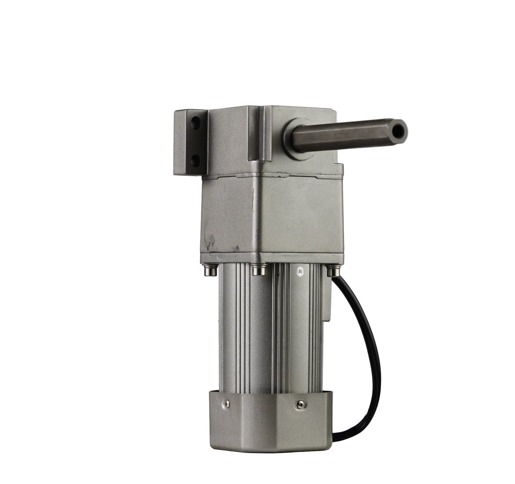
An improperly specified motor results in premature mechanical failure. It causes massive energy waste and costly unplanned downtime. Making the wrong purchasing decision puts your entire production line at risk. AC induction motors serve as standard industrial workhorses today. However, pairing them correctly requires precise application matching. You must integrate the right reduction mechanism and electrical control strategy. This prevents catastrophic overloading and poor system efficiency. We created the following evaluation framework specifically for engineers and procurement teams. It helps you bridge the gap between mechanical requirements and commercial realities. You will learn how to calculate loads accurately before evaluating catalogs. We will show you how to select the ideal physical orientation. You will also discover how to match electrical controls perfectly. Follow these detailed steps to ensure your next setup runs efficiently from day one.
Key Takeaways
Sizing is crucial: Over-specifying torque wastes capital and space; under-specifying leads to rapid thermal failure.
Orientation matters: Space constraints and load types dictate whether a right angle, parallel, or linear configuration is necessary.
Control dictates performance: Dynamic applications require specific control methods like a frequency converter to manage speed without losing torque.
Define the Mechanical Load and Output Requirements
You must calculate exact mechanical demands before looking at catalogs. Guessing load requirements guarantees future breakdowns. Use a structured approach to define your true operational needs.
Calculate Required Operating Torque
You need to distinguish between continuous running torque, starting torque, and peak torque. Continuous torque handles normal, steady-state operations. Starting torque overcomes initial physical inertia. Peak torque manages sudden overload conditions during operation. You must size your unit to handle peak moments without stalling the machine. Failing to account for startup inertia often causes immediate stalling.
Determine Output Speed (RPM)
Finding the right output speed requires basic reduction math. You calculate the necessary reduction ratio based on your target output speed. Divide the base motor speed by your desired final RPM. This specific ratio dictates the internal gearing layout. Engineers often forget to account for minor speed variations under heavy loads. Always verify the rated speed under full load conditions.
Account for Radial and Axial Loads
External attachments create severe mechanical stress. Overhung loads from sprockets or pulleys push aggressively against the shaft. This impact alters the required bearing life drastically. It also dictates the optimal shaft size of your gear reducer. You must verify these exact forces against published manufacturer limits. Excessive radial loads bend shafts and destroy seals rapidly.
Safety Margins
Engineers often add a "50% just in case" safety factor out of fear. This arbitrary sizing creates massive system inefficiencies. Oversized motors run poorly at partial load conditions. They decrease overall efficiency and worsen your facility's power factor. Rely on exact calculations instead of guesses. An oversized AC Gear Motor wastes capital and consumes unnecessary physical space.
Common Mistake: Ignoring the difference between running torque and starting torque leads to burnt-out windings during machine startup phases.
The force required to keep the machine moving at a steady pace.
Dictates the baseline thermal capacity and standard sizing.
Starting Torque
The initial force required to break static friction and accelerate.
Determines the minimum power needed to prevent stalling on startup.
Peak Torque
The maximum short-term force encountered during sudden jams.
Dictates the mechanical strength required for internal gears and shafts.
Match the Gearbox Orientation to Spatial and Application Constraints
Every machine design features rigid spatial limits. You must select a configuration fitting your physical footprint precisely. Each internal orientation offers distinct mechanical advantages and disadvantages.
AC Parallel Shaft Gear Motor
Specify an AC parallel shaft gear motor for applications demanding high torque efficiency. These units offer extremely low backlash during operation. They work perfectly when your inline space allows for a longer overall footprint. Parallel setups primarily use helical or spur gears internally. They transfer power directly and run much cooler than alternative designs.
Right Angle AC Gear Motor
Sometimes your design footprint remains incredibly tight. A right angle AC gear motor solves strict spatial constraints easily. The motor sits perfectly perpendicular to the output shaft. However, you must consider efficiency trade-offs carefully here. Worm gears offer compactness but generate significant heat through sliding friction. Bevel gears provide better efficiency at a higher initial setup cost.
Linear Gear Motor
Some applications require pushing or pulling rather than traditional rotating. A linear gear motor converts rotary motion into precise linear actuation. We see these utilized heavily in automated material handling sectors. Packaging lines rely on them extensively for exact positioning tasks. They eliminate the need for external lead screws in many designs.
Small AC Gear Motor Applications
Compact machines demand highly miniaturized internal components. You must balance physical size against critical heat dissipation. A small AC gear motor fits tight control enclosures very well. However, you must guarantee adequate airflow around the housing. Miniaturization often restricts natural thermal convection, leading to fast overheating.
Best Practice: Always request 3D CAD models early in your design phase. Check for physical interferences before finalizing your orientation choice.
Chart: Comparison of Gearbox Orientations
Orientation
Primary Advantage
Typical Efficiency
Best Use Case
Parallel Shaft
High power transmission
95% - 98%
Conveyors with inline space
Right Angle (Worm)
Extremely compact footprint
50% - 85%
Tight corners, simple hoists
Right Angle (Bevel)
Compact with high strength
90% - 95%
Heavy duty tight-space loads
Evaluate Electrical Integration and Speed Control
Electrical compatibility remains just as vital as mechanical fit. A perfect mechanical match fails quickly if the electrical integration falls short. You must align your power specs and control mechanisms.
Input Power Specifications
You must verify your facility's power supply first. Mismatched voltages destroy windings instantly. Check these essential parameters:
Phase Type: Single-phase works well for lighter loads. Three-phase power dominates heavy industrial manufacturing setups.
Voltage Standards: Match the voltage standard precisely. Common ratings include 115V, 230V, and 460V configurations.
Frequency Compliance: Verify regional frequency compliance carefully. You might need 50Hz for European setups or 60Hz for North American facilities.
Dynamic Control Needs
Your specific application dictates your overall control strategy. Use an AC motor speed controller for simple, standalone variable speed tasks. It handles basic manual adjustments easily. Conversely, you should integrate a frequency converter for complex automation. It manages automated acceleration and deceleration profiles perfectly. It also maintains high torque output at very low operating speeds.
Inverter-Duty Ratings
Standard motors struggle terribly under complex modern controls. You must ensure the motor winding insulation carries a specific inverter-duty rating. Variable frequency drives introduce severe electrical voltage spikes. They create corona discharges inside the casing. Standard insulation breaks down prematurely under these harsh conditions. Inverter-duty ratings prevent this rapid electrical degradation entirely.
Duty Cycle Assessment
Identify exactly how often your system runs daily. Differentiate between continuous duty and intermittent cycles.
Continuous Duty (S1): The motor runs at a constant load long enough to reach thermal equilibrium.
Intermittent Duty: The motor starts and stops frequently, never reaching a stable thermal state.
Frequent starts generate massive amounts of internal heat. You must specify appropriate external cooling requirements based on your cycle.
Assess Operating Environment and Compliance Standards
Industrial environments destroy unprotected equipment rapidly. You must evaluate surrounding hazards carefully before finalizing your purchase. Environmental factors dictate highly specialized design features.
Ingress Protection (IP Rating)
Correlate known environmental hazards to specific IP protection requirements. Airborne dust and debris require completely sealed enclosures. Food processing plants demand rigorous high-pressure washdown capabilities. Standard factory floors often use IP55 ratings successfully. Harsh washdown zones require strict IP69K protection. Match the ingress rating to your absolute worst-case daily scenario.
Thermal Constraints
Ambient temperature extremes affect internal performance drastically. High-heat environments demand specific mechanical cooling methods. Totally Enclosed Fan Cooled (TEFC) designs work well generally. Totally Enclosed Non-Ventilated (TENV) options suit highly contaminated areas better. Extreme cold requires specialized synthetic lubricants. Standard factory grease hardens and fails completely below freezing.
Industry Certifications
Geographic deployment strictly dictates regulatory compliance marks. North American facilities require NEMA and UL safety certifications. European markets demand IEC and CE compliance legally. Specific industries enforce their own strict internal regulations. Food-grade applications require specialized epoxy paint and non-toxic lubrication. Chemical plants often require explosion-proof ATEX certifications. Always verify regional laws.
Common Mistake: Deploying standard vented motors in dusty environments clogs the internal rotors, causing rapid thermal failure.
How to Vet an AC Gear Motor Supplier
The best hardware fails quickly without proper manufacturer backing. You must evaluate the manufacturer just as rigorously as the physical product. A reliable AC gear motor supplier acts as a long-term strategic partner.
Engineering and Customization Support
Look for deep application engineering assistance early on. The best suppliers review your initial load calculations carefully. They provide accurate 3D CAD models for your machine design phase. They also offer customized output shaft configurations readily. Flexible mounting options show strong internal manufacturing capabilities. Avoid suppliers who only sell off-the-shelf catalog configurations.
Supply Chain Resilience
Material shortages halt modern production lines instantly. Assess average supplier lead times critically. Ask about their domestic inventory levels for standard replacement units. Verify the long-term availability of critical replacement parts. Strong supply chains keep your facility running smoothly during global disruptions. Ask where they source their raw castings from.
Testing and Quality Assurance
Demand hard proof of reliability upfront. Look for documented factory acceptance testing (FAT) procedures. Ask for published mean time between failures (MTBF) data sheets. Read the standard warranty terms closely. Transparent, lengthy warranties indicate strong manufacturer confidence. A supplier hiding test data usually produces inconsistent mechanical quality.
Best Practice: Request a factory tour or virtual audit to verify their actual testing equipment and quality control processes.
Conclusion
A successful purchase relies heavily on strict alignment across multiple engineering disciplines. You must balance mechanical torque and physical spatial constraints perfectly. You also need precise electrical control matching your specific operating environment. Missing any single evaluation factor guarantees premature mechanical or electrical failure.
Take time to compile your exact mechanical load data now. Document your intended duty cycle and physical dimensional constraints clearly. Gather these details before ever contacting any manufacturer. Solid baseline data prevents costly initial sizing errors.
Consult an application engineer early in your design process. Download a detailed mechanical sizing worksheet to track your metrics. Request a comprehensive technical quote based on your exact mathematical calculations. Proactive planning secures highly reliable long-term machine performance.
FAQ
Q: Can I run a standard AC gear motor with a frequency converter?
A: Running a standard non-inverter-duty motor with a VFD creates massive risks. The frequency converter introduces sharp electrical voltage spikes. This degrades standard winding insulation rapidly. Standard internal fans also fail to cool the unit at low running speeds. You must upgrade to an inverter-duty rated motor for safe operations.
Q: What is the difference between a gear reducer and a gear motor?
A: A gear reducer acts as a standalone mechanical gearbox. It requires you to mount and align an external motor manually. An AC gear motor represents an integrated package. The manufacturer aligns and seals the motor and reducer together permanently. This integration eliminates alignment issues completely.
Q: How do I choose between a right angle and a parallel shaft configuration?
A: Your available mounting space primarily dictates this critical choice. Tight, perpendicular footprints strictly require right-angle units. If you possess inline space, prioritize parallel shaft models. Parallel configurations transfer physical power much more efficiently than right-angle worm gears. Always choose parallel setups when spatial constraints permit.
Q: Why is my AC gear motor overheating?
A: Overheating usually stems from common implementation errors. You might be exceeding the original rated duty cycle. Operating continuously below the cooling fan's effective speed range causes rapid heat buildup. Additionally, ambient factory temperatures may exceed your specific internal insulation class limits. Verify your loads against original specifications immediately.