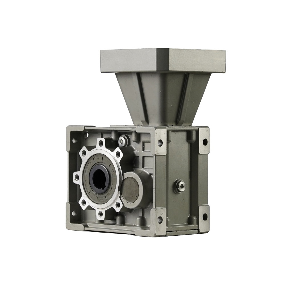
Designing or upgrading right-angle power transmission systems requires balancing torque capacity, space constraints, and energy efficiency. Mechanical engineers often face difficult choices when evaluating these essential drive components. The core dilemma involves choosing between two very prominent technologies. Both hypoid and bevel gears transmit power at precise 90-degree angles. However, their underlying geometric differences fundamentally alter their performance profiles, routine maintenance requirements, and long-term lifecycle expenses. Misjudging these specific mechanical factors frequently leads to premature system failures and costly equipment downtime. This comprehensive article provides a clear, engineering-focused framework to effectively evaluate these two gear types. You will learn exactly how distinct axis alignments affect load distribution, sliding friction, and thermal generation. Ultimately, our goal is ensuring you confidently specify the correct transmission unit for your specific load, speed, and spatial design requirements.
Key Takeaways
Geometry: Bevel gears operate on intersecting axes; a hypoid gear operates on non-intersecting, offset axes.
Performance Tradeoff: Hypoid gears offer higher torque capacity and quieter operation due to a larger pinion and higher contact ratio, but sacrifice a small percentage of mechanical efficiency compared to spiral bevel gears.
Maintenance: The sliding action of hypoid gears generates more heat, strictly requiring Extreme Pressure (EP) lubricants, unlike standard bevel configurations.
Application: Spiral bevels are ideal for high-speed, high-efficiency needs; hypoids excel in high-torque, space-constrained, or noise-sensitive environments.
The Fundamental Geometry: Intersecting vs. Offset Axes
To understand the mechanical differences, we must examine how engineers construct the theoretical pitch surfaces. These invisible geometric boundaries define how gear teeth engage under load. The fundamental distinction lies purely in axis alignment.
Spiral Bevel Gear Mechanics
Traditional configurations rely on a completely intersecting design. The pinion and the driven ring gear meet precisely at a common central point.
Axes intersect perfectly, typically forming a rigid 90-degree angle.
The pinion and gear share a common center plane.
Engineers base the design on conical pitch surfaces.
Motion relies primarily on pure rolling friction.
Rolling action naturally minimizes internal heat generation.
Because the teeth roll against one another smoothly, they avoid severe scraping actions. This makes them highly efficient. You often find them in high-speed applications where thermal expansion causes alignment issues.
Hypoid Gear Mechanics
A hypoid gear fundamentally alters this standard geometry. Instead of meeting at a central point, the input shaft shifts vertically.
The pinion sits offset above or below the center of the ring gear.
Engineers base this design on hyperboloids of revolution rather than simple cones.
The unique offset allows the pinion to feature a distinct spiral angle.
This geometry creates a combined rolling and sliding action during tooth engagement.
This structural shift defines the entire performance profile. It provides distinct mechanical advantages but introduces specific tribological challenges. We must address these friction challenges during the design phase.
Performance Evaluation: Torque, Efficiency, and Noise
You cannot specify a drive system based on geometry alone. We must evaluate how these physical shapes translate into real-world mechanical performance. The three primary evaluation metrics include torque capacity, energy efficiency, and acoustic output.
Torque Capacity and Load Distribution
Load handling separates these two technologies distinctly. Because of the vertical drop, a hypoid gearbox utilizes a much larger pinion than a standard intersecting unit of the exact same ratio. A larger pinion contains thicker, stronger teeth.
Furthermore, the unique geometry dramatically increases the contact ratio. This means more individual teeth mesh simultaneously. Multiple teeth sharing the load allows the unit to handle severe shock loads effortlessly. It transmits far greater torque within the exact same housing footprint.
Efficiency Tradeoffs (Transparent Assessment)
Mechanical efficiency refers to how much input power successfully reaches the output shaft. Heat generation represents lost power.
A standard spiral bevel gearbox boasts exceptionally high efficiency. It often hits 95-98% under optimal conditions. The minimal sliding friction keeps energy losses negligible. Conversely, offset configurations experience inherent sliding along the gear teeth flanks. This heavy sliding introduces immediate thermal loss. Efficiency typically drops to 85-90%. The exact percentage depends heavily on the specific offset ratio and operational speed.
Acoustic Profile (Noise and Vibration)
Industrial noise pollution matters greatly. High-speed factory automation demands strict acoustic control. The heavy sliding mesh of offset gears provides an unexpected benefit here. It results in significantly smoother operation. Gradual tooth engagement absorbs micro-vibrations effectively. This creates a much quieter machine. Quiet operation proves critical for consumer-facing equipment or heavily noise-regulated manufacturing environments.
Comparison Summary Table
Evaluation Metric
Spiral Bevel Technology
Hypoid Technology
Axis Alignment
Intersecting at center
Offset (above/below center)
Primary Friction Type
Rolling action
Combined rolling and sliding
Mechanical Efficiency
95% - 98%
85% - 90%
Torque Density
Moderate
Exceptionally High
Acoustic Output
Moderate to High
Smooth and Quiet
Spatial Configuration and Machine Design Flexibility
Factory floor space costs a premium. Machine builders constantly attempt to shrink equipment footprints. Traditional right-angle drives sometimes present physical layout roadblocks. The specific shaft alignments dictate entirely different housing structures.
Solving Physical Clearance Issues
Standard intersecting drives block one another. The input shaft points directly at the output shaft centerline. You cannot easily pass cables or secondary drive shafts through this intersection.
Utilizing offset axes solves this precise clearance issue. The input and output shafts cross without interfering. They occupy different geometric planes. This enables engineers to design highly compact machine layouts. You can pass drive shafts directly past the gear set.
Additionally, you can mount the drive motor significantly lower in the chassis. Lowering heavy motors drops the overall machine center of gravity. Automotive differentials and heavy mobile robotics rely on this technique to prevent tipping during rapid maneuvers.
Ratio Versatility and Stage Reduction
Gear ratio defines speed reduction. Standard right-angle units often max out at lower single-stage reduction ratios. Pushing them further weakens the pinion teeth too much.
Offset geometries bypass this limitation entirely. They can easily achieve higher single-stage reduction ratios. Ratios of 10:1 or greater remain common and highly durable. Achieving this massive reduction in one single step potentially eliminates the need for secondary gearing. You can often remove an extra gear reducer stage from the assembly entirely. Fewer stages mean fewer moving parts, reducing overall system complexity.
Implementation Risks: Lubrication, Thermal Limits, and Wear
Every engineering advantage carries a specific cost. The heavy sliding friction defining these offset units introduces serious tribological and thermal challenges. You must mitigate these risks actively during the specification process.
The Lubrication Mandate (Risk Mitigation)
The high sliding velocity aggressively wipes away standard oil films. Normal mineral oils simply cannot withstand the shearing forces. High pressure squeezes the oil out of the microscopic gaps between the teeth. Bare metal then contacts bare metal.
This friction strictly requires specific EP (Extreme Pressure) gear oil additives. These chemical additives typically contain sulfur-phosphorus compounds. They bond directly to the metal surfaces under high heat. This prevents metal-to-metal contact, severe scoring, and premature mechanical failure. Never run an offset system on standard hydraulic or non-EP gear oil.
Active Thermal Management
Higher sliding friction inevitably means higher operating temperatures. Heat breaks down oil viscosity rapidly. You must assess duty cycles strictly.
Calculate the continuous running time versus rest periods.
Determine the ambient environment temperature.
Assess whether natural convective cooling handles the thermal load.
Continuous, high-speed operation may require active external cooling systems. You might need oil pumps and radiators. In contrast, a purely intersecting equivalent might survive easily on natural convection due to lower internal friction.
Manufacturing Complexities and Replacement Rules
Offset profiles require incredibly complex machining. Manufacturers use specialized CNC equipment to cut the hyperbolic curves. After cutting, the factory laps the pinion and ring gear together. They run them against each other using an abrasive compound.
This lapping process marries the two specific parts permanently. They become a matched set. If a tooth breaks in the field, a strict replacement rule applies. You cannot swap just the pinion or the ring gear independently. A field replacement always requires matching lapped pairs to ensure proper contact patterns.
Shortlisting Logic: Which Gear Reducer Fits Your Application?
Selecting the correct technology requires matching system constraints to component strengths. Neither option proves universally superior. Follow this shortlisting logic to narrow down your immediate options.
When to Specify a Spiral Bevel Gearbox
These units prioritize absolute efficiency and thermal stability.
Primary Drivers: High continuous speeds, maximum energy efficiency, low heat generation requirements.
Typical Applications: High-speed packaging machinery, industrial pump drives, standard material conveyors, and continuous-duty paper mills.
If your machine runs continuously at maximum speed, choose this option to avoid catastrophic overheating.
When to Specify a Hypoid Gearbox
These units prioritize torque density, compactness, and acoustic control. A modern helical hypoid gearbox combines offset technology with helical input stages for massive torque delivery.
Primary Drivers: Space restrictions requiring crossed shafts, extremely high shock loads, strict workplace noise limitations, and demand for high single-stage reduction.
Typical Applications: Automated Guided Vehicles (AGVs), precise motion control systems, multi-axis robotics, and heavy material handling lifts.
If your application requires lifting heavy, sudden loads in tight spaces, this technology outperforms all alternatives.
Next-Step Action
Begin by mapping out your required safety factor accurately. Determine the difference between your continuous running torque and your maximum peak shock torque. Next, outline your absolute thermal limitations based on the factory environment. Finally, consult with an application engineer. They can run long-term lifecycle comparisons, balancing the energy costs of intersecting gears against the profound space and torque benefits of offset units.
Conclusion
The choice between these right-angle technologies relies on a calculated engineering tradeoff. You must balance mechanical efficiency against absolute torque, packaging flexibility, and operating noise. Spiral units dominate continuous, high-speed environments where heat dissipation poses a major threat. Conversely, offset geometries excel in tight spaces where heavy shock loads and noise reduction matter most. Understanding these fundamental geometric principles prevents costly field failures.
Take time to map your physical space constraints before ordering parts. Prompt your engineering team to download a comprehensive sizing guide. We encourage you to reach out and discuss your custom hypoid gear unit requirements with a technical sales specialist. They will perform application-specific torque and thermal calculations to guarantee success.
FAQ
Q: Can I replace a spiral bevel gear with a hypoid gear?
A: Usually, no. The spatial layouts differ significantly. The required pinion offset demands a specifically designed housing block. You cannot simply drop an offset gear set into a standard intersecting-axis casing. You must completely redesign the machine housing to accommodate the vertically shifted shaft alignments.
Q: Why does a hypoid gear unit require different oil?
A: The engagement involves heavy, continuous sliding friction. This aggressive sliding quickly shears and wipes away standard lubricating films. You must use gear oils fortified specifically with Extreme Pressure (EP) additives. These chemical additives bond to the metal under heat, preventing direct metal-to-metal contact and stopping rapid tooth scoring.
Q: Is a helical hypoid gearbox better than a standard worm gear reducer?
A: Yes, primarily regarding operational efficiency. A standard right-angle worm unit usually operates between 50-70% efficiency due to massive internal sliding friction. A modern helical and offset combination easily achieves around 90% efficiency. This dramatic reduction in thermal energy loss makes them a high-return upgrade.