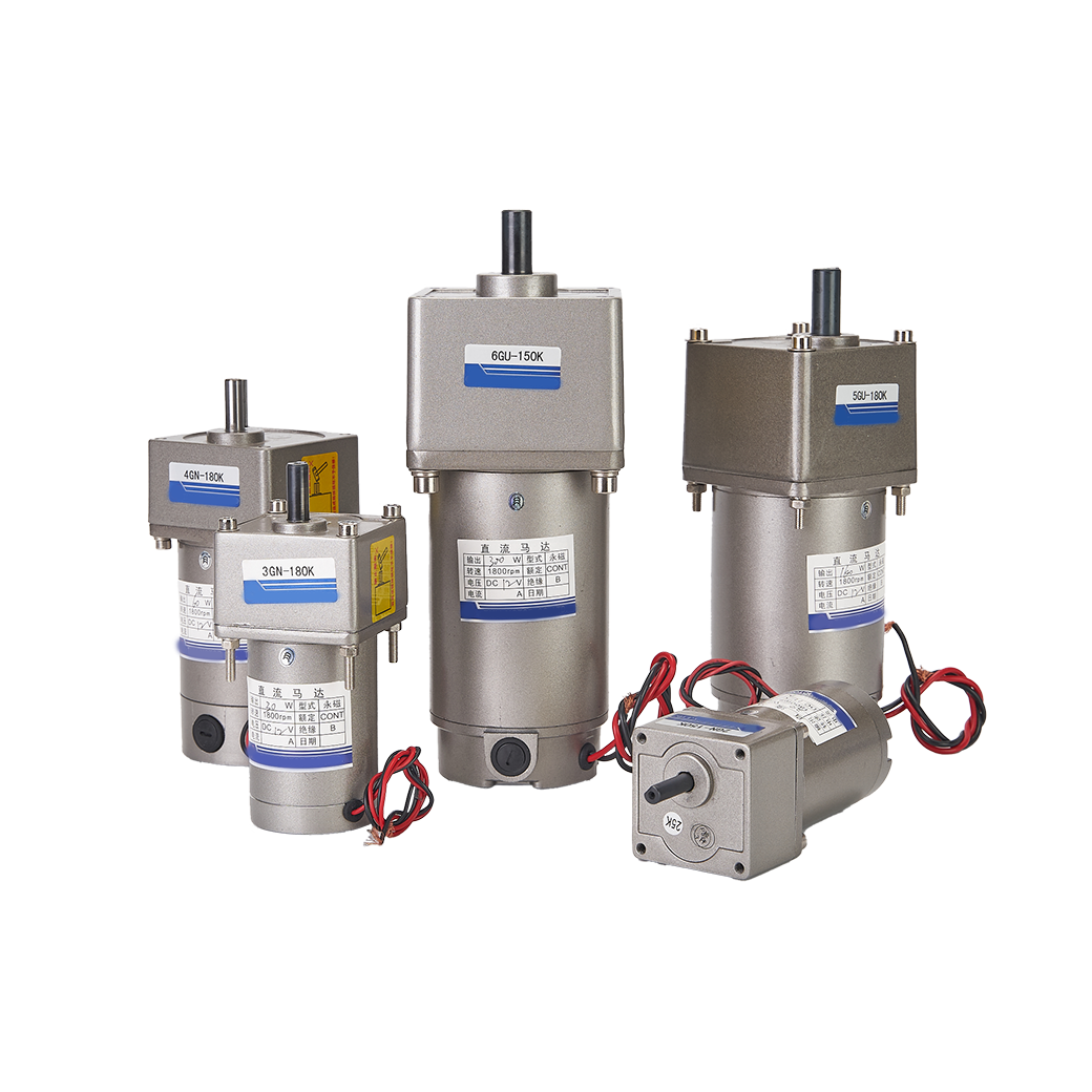
In industrial automation, hardware reliability directly dictates production output. Specifying an incorrect motor often causes premature failure. This mistake generates expensive factory downtime. Conversely, over-specifying equipment needlessly inflates capital expenditure. Oversized motors also waste valuable electrical energy. You need a structured, engineering-first evaluation framework. We provide this exact approach below. You will learn how to match motor characteristics directly to your specific requirements. We analyze load, speed, and environmental demands in detail. This guide begins by analyzing mechanical loads. Then, we evaluate different motor architectures. Next, we cover strict sizing specifications. Finally, you will explore vital system integration components. Following these steps ensures maximum operational efficiency.
Key Takeaways
Base your DC motor selection on the exact motion profile (continuous vs. intermittent duty) rather than peak power alone to avoid thermal degradation.
Brushless DC (BLDC) motors offer a lower Total Cost of Ownership (TCO) for high-duty automation despite higher initial controller costs, due to zero brush maintenance.
Operating environments dictate motor selection as much as torque; IP ratings, thermal limits, and EMI shielding are non-negotiable compliance factors.
Accurate sizing requires factoring in the entire powertrain system, including gearboxes, drivers, and feedback mechanisms (encoders).
Establishing Your Motion Profile and Load Requirements
We must first define the exact mechanical work required. Map out your ideal physical outcome before looking at motor specifications. You need clear success criteria to avoid engineering mistakes.
Define the Success Criteria
Determine exactly what the motor must move. Ask yourself if the system requires rapid positioning or steady-state operation. Defining the end goal ensures you evaluate the correct performance metrics.
Calculate Load Characteristics
Engineers categorize mechanical loads into two primary types. You must calculate both to size your system correctly.
Inertial Load: This dictates the force needed for starting and stopping. Mass resists changes in velocity. High-speed robotics and automated pick-and-place systems rely heavily on overcoming inertial loads. You must calculate the peak torque required to accelerate the payload safely.
Frictional Load: This represents the consistent, ongoing force required to maintain movement. Overcoming mechanical resistance defines this load type. Heavy conveyor belts dragging across guide rails present massive frictional loads. Your equipment must supply adequate continuous torque to prevent stalling.
Determine the Duty Cycle
Duty cycle directly dictates your thermal management strategy. Continuous duty means the machine runs uninterrupted for hours. This scenario requires robust thermal dissipation. Intermittent duty involves brief operation periods followed by rest. The resting phase allows internal windings to cool. Intermittent duty lets you leverage peak torque capabilities safely.
Speed Constraints
Always document the maximum RPM required for your process. Some processes require a single, constant speed. Other systems demand highly variable speed control. Identifying this early limits your future controller options appropriately.
Evaluating Primary DC Motor Technologies for Automation
Once you define your load profile, you must select the optimal hardware architecture. Each technology offers distinct advantages for specific industrial applications.
Brushed DC Motors
Engineers traditionally select these units for simple, budget-conscious control applications. Think of basic indexing belts or non-critical automated facility doors. A standard DC Motor provides immense value when complex controls remain unnecessary.
Pros: They offer an exceptionally low initial purchase price. Engineers appreciate the straightforward two-wire control scheme. They also deliver fantastic starting torque for heavy static loads.
Risks/Realities: Internal carbon brushes degrade over time. This wear mandates strictly scheduled maintenance. Furthermore, physical brush arcing creates sparks. These sparks generate severe electromagnetic interference. They also pose extreme hazards in explosive atmospheres.
Brushless DC Motors (BLDC)
These units dominate high-speed, high-reliability precision automation sectors. CNC machining centers, automated guided vehicles (AGVs), and multi-axis robotic arms rely heavily on this technology.
Pros: They feature an incredibly long lifespan. Bearing failure represents the only typical mechanical limitation. They boast an outstanding power-to-weight ratio. The lack of friction ensures excellent thermal characteristics. Choosing a modern Brushless DC motor future-proofs your production line.
Risks/Realities: They require sophisticated electronic commutation. You cannot simply connect them directly to a power rail. This complexity demands intelligent drives, increasing upfront capital expenditure.
DC Gear Motors
You integrate these specialized units when applications demand massive torque at very low speeds. Direct-drive setups often fail under these specific conditions. Adding planetary or spur gearheads creates a significant mechanical advantage. However, you must carefully evaluate the resulting tradeoffs. Gearing increases the physical footprint of the assembly. It also introduces slight mechanical efficiency losses. Carefully evaluate these factors when specifying a heavy-duty Electric DC Gear Motor for demanding industrial environments.
Critical Performance Specifications for Shortlisting
Now we translate your basic motion profile into concrete engineering specifications. You must evaluate these technical parameters carefully.
Torque Ratings (The Sizing Core)
Torque metrics form the absolute foundation of reliable motor sizing.
Continuous (Rated) Torque: This indicates the maximum rotational force the unit delivers indefinitely. The hardware achieves this without exceeding internal thermal limits. Always align this figure with your frictional load calculations.
Stall/Peak Torque: This represents the absolute maximum output available for brief bursts. You utilize this strictly for sudden acceleration or overcoming static friction. Never size continuous operations based on peak torque metrics. Doing so guarantees rapid thermal failure.
Speed-Torque Curve Analysis
Reputable manufacturers provide detailed speed-torque curves. You must learn to read these charts accurately. Rotational speed naturally drops as physical load increases. You must ensure your intended operating point falls squarely within the continuous efficiency zone. If your operation requires running near the stall limit, overheating becomes imminent.
Voltage and Power Supply
You must match hardware voltage ratings to your available industrial power rails. Common industrial options include 12V, 24V, and 48V systems. We highly recommend utilizing higher voltage systems whenever possible. Higher voltages allow the equipment to achieve identical power outputs while drawing significantly lower current. Lower current draw reduces wire gauge requirements. It also drastically minimizes I⊃2;R heat losses throughout your facility.
Thermal Constants
Always inspect internal winding insulation classes during evaluation. Insulation degrades quickly under extreme heat. Class F insulation safely withstands operating temperatures up to 155°C. Class H insulation provides superior protection up to 180°C. You must also consider the ambient temperature of your factory floor. High ambient facility temperatures severely degrade operational performance. They prevent effective convective cooling.
Operating Environment and Compliance Realities
The physical environment dictates hardware survival. High performance metrics mean nothing if ingress or trapped heat destroys the internal components.
Ingress Protection (IP) and NEMA Ratings
Environmental hazards destroy unprotected electrical equipment rapidly. Heavy airborne dust in textile milling or CNC machining demands tight sealing. Washdown environments in food processing require minimum IP65 or IP67 ratings. Always match the enclosure specification directly to the localized hazard.
Table: Standard Ingress Protection for Automation Environments
Hazard Type
Automation Environment
Required Minimum Rating
Airborne Dust & Debris
Textile milling, Woodworking, CNC
IP65 Enclosure
Low-Pressure Water Jets
Beverage bottling, Basic washdown
IP66 Enclosure
Submersion & High-Pressure
Meat processing, Heavy sanitation
IP67 Enclosure
Thermal and Altitude Derating
Enclosed automation cabinets trap significant heat over time. This restricts crucial airflow around the equipment. Airflow restrictions demand deliberate thermal derating of the expected continuous torque. High altitude environments also present unique challenges. Thinner air provides drastically reduced convective cooling capacity. You must derate performance specifications accordingly when deploying systems in elevated regions.
Electromagnetic Compatibility (EMC/EMI)
Electrical noise often interferes with programmable logic controllers (PLCs). Sensitive factory sensor networks also suffer from severe signal degradation. Brushed architectures generate severe broadband interference via physical arcing. High-speed BLDC switching also emits high-frequency noise. You must implement strict shielding protocols. Proper grounding techniques remain non-negotiable for stable automation.
Industry-Specific Compliance
Certain industries impose strict regulatory standards. Explosive atmospheres in chemical plants require specialized ATEX-rated explosion-proof enclosures. Food-grade automation mandates FDA-compliant exterior coatings. You must also specify non-toxic, food-safe internal lubricants.
System Integration and Component Compatibility
Selecting the raw hardware represents just one step. You must integrate it seamlessly into the broader automation ecosystem.
Drive and Controller Compatibility
Hardware performs only as well as its connected control electronics allow. You must pair sophisticated systems with a highly compatible Motor Driver. First, decide whether your application requires precise closed-loop algorithms. Closed-loop systems provide exact positioning data. Open-loop controllers offer a simpler, budget-friendly alternative for less demanding tasks.
Feedback Mechanisms (Encoders)
Evaluate your strict requirements for position and velocity feedback. High-precision robotics require external optical or magnetic encoders. These sensors report exact rotor positions back to the main logic controller. Conversely, basic spinning applications often rely entirely on sensorless control algorithms. Sensorless control utilizes back-EMF measurements, eliminating the need for delicate external sensors.
Maintenance Overheads
Compare the heavy labor demands of standard brushed systems against modern alternatives. Replacing carbon brushes requires halting production. It demands manual labor and specialized technicians. Modern brushless equivalents provide an "install and forget" nature. This architecture drastically reduces labor interventions. Eliminating scheduled teardowns keeps your automated lines running efficiently year-round.
Shortlisting Next Steps
Create a rigid prototyping checklist before authorizing mass procurement.
Request highly accurate 3D CAD models from the manufacturer.
Verify mounting face and shaft dimensions against standard NEMA frame sizes.
Order a single sample unit for physical thermal testing.
Run simulated loads matching your exact production environment.
If you encounter integration difficulties, explore specialized professional services. Expert engineers can review your load calculations and validate your final design.
Conclusion
Choosing the correct equipment requires a strict balancing act. You must align physical load physics, harsh environmental constraints, and available integration space. Do not arbitrarily oversize your system. Applying a massive 20-30% safety factor creates severe inefficiencies. It forces inefficient controller pairing and wastes valuable cabinet space.
Actionable next steps include documenting your exact load characteristics immediately. Then, match technology types to your operational environment. Always prototype and run thermal tests before mass deployment. We strongly encourage consulting a specialized integrator. Submit your complete motion profile to the manufacturer's engineering team. Let experts validate your math before finalizing your hardware architecture.
FAQ
Q: Can I run a 24V DC motor on a 12V supply?
A: Yes, but you will experience a proportional drop in both speed and torque. Operating at half the rated voltage cuts overall performance significantly. This introduces a severe risk of stalling under typical loads. Stalling rapidly overheats the internal copper windings and eventually destroys the system.
Q: How do I choose between a stepper motor and a BLDC motor for automation?
A: Stepper motors excel in open-loop simplicity. They provide massive holding torque at zero speed, making them ideal for precise, low-speed positioning. BLDC motors deliver superior high-speed efficiency and closed-loop performance. Choose BLDC when your application demands rapid acceleration, continuous high-speed operation, and dynamic load adaptation.
Q: What is the difference between peak torque and continuous torque in a DC motor?
A: Continuous torque represents the maximum mechanical output the unit sustains indefinitely. It does this without exceeding safe thermal limits. Peak torque represents the absolute maximum output available, but only for brief acceleration bursts. Relying on peak torque for continuous duty cycles guarantees catastrophic thermal failure.
Q: Why do BLDC motors require a dedicated controller?
A: Traditional units use physical carbon brushes to mechanically switch current direction. BLDC technology eliminates these physical brushes entirely. Instead, they require sophisticated electronic commutation. A dedicated controller rapidly pulses current to specific stator coils at precise microsecond intervals. This continuous electronic sequencing maintains smooth rotor movement.