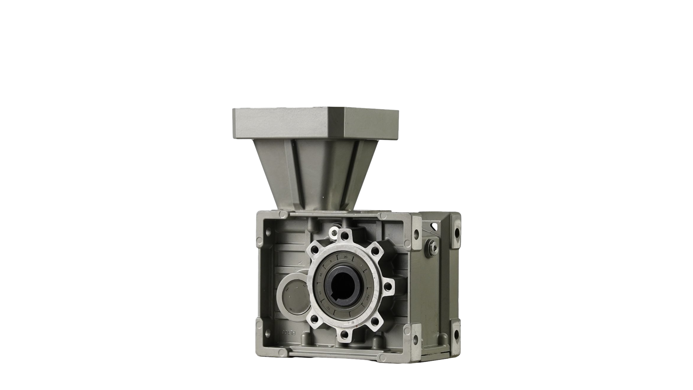
Right-angle power transmission usually forces engineers to compromise between torque capacity, operating noise, and spatial footprint. You often find yourself trading efficiency for size, or durability for quieter operation. While standard bevel or worm gears suit basic requirements, complex industrial systems demand a precise balance. They require high efficiency, compact design, and heavy load capacities to function reliably.
Specifying a hypoid gear is a strategic engineering decision driven by the need for an offset axis and superior meshing stiffness. You do not choose this component lightly. This guide breaks down where these gears are deployed across heavy industries. We will evaluate how they stack up against traditional alternatives. Finally, we will uncover the implementation realities required for long-term reliability in demanding environments.
Key Takeaways
Core Utility: Hypoid gears dominate applications requiring right-angle power transmission with non-intersecting shafts (an offset axis).
Primary Sectors: Widely used beyond automotive differentials, acting as the standard in robotics, conveying systems, and as a durable wind application gearbox.
Performance vs. Alternatives: Offers 90–95% efficiency—outperforming worm gears in energy savings and outperforming a spiral bevel gearbox in torque density and noise reduction.
Implementation Caveat: The offset design creates sliding friction, mandating precise alignment and specialized Extreme Pressure (EP) lubrication to prevent rapid wear.
The Engineering Problem: Why Specify a Hypoid Gear?
Standard right-angle gearboxes often struggle under modern industrial constraints. They take up too much physical space or generate excessive noise under high torque loads. In high-speed manufacturing environments, noise and vibration compromise both worker safety and machine precision. Engineers need a robust solution. They need a system capable of handling massive shock loads without expanding the machine footprint.
This is where the offset geometry becomes invaluable. An offset axis gearbox allows the pinion to be positioned above or below the center of the ring gear. This unique layout enables continuous, uninterrupted shaft routing. You avoid the physical interference common in intersecting shaft designs. Furthermore, this offset geometry directly lowers the center of gravity in mobile applications. A lower center of gravity improves vehicle stability and maximizes usable chassis space.
The internal geometry also drastically improves performance. The unique tooth profile allows multiple teeth to mesh simultaneously. This high contact ratio distributes the operational load over a much larger surface area. It directly translates into superior shock-load resistance. The gradual tooth engagement also dampens vibration. You achieve much quieter operation compared to a standard gear reducer.
Best Practice: Always map out your exact spatial clearances during the initial 3D modeling phase to fully leverage the offset shaft advantage.
Common Mistake: Failing to account for the increased radial loads placed on bearings when maximizing the pinion offset distance.
Core Environments: Where is a Hypoid Gearbox for Industrial Applications Used?
Industrial environments push mechanical components to their absolute limits. A hypoid gearbox for industrial applications excels in high-stress, precision-focused settings. We see this technology deployed across multiple sectors demanding absolute reliability.
Heavy-Duty Automation & Conveying
Modern logistics rely heavily on automated guided vehicles (AGVs) and dense packaging lines. These systems operate under strict spatial constraints. They require an all-round installation gearbox capable of delivering intense torque within a limited footprint. The offset design allows for flexible mounting orientations. Engineers can tuck the motor and transmission neatly into the AGV chassis, leaving more room for battery payloads.
Renewable Energy Sector
Wind turbines operate in brutal, unpredictable environments. Engineers deploy this technology as a highly reliable wind application gearbox, specifically within pitch and yaw drives. These critical drives must hold blade positions accurately under extreme, shifting aerodynamic loads. The high meshing stiffness prevents the system from being back-driven during sudden wind gusts, ensuring the turbine maintains peak aerodynamic efficiency.
Precision Robotics & Machine Tools
Robotic arms, CNC rotary tables, and automated welding stations demand minimal backlash. Precision is non-negotiable. The inherent structural stiffness maintains strict positional accuracy during high-speed, dynamic movements. When a robotic arm halts abruptly, the robust gear teeth absorb the payload inertia. They do this without losing positional calibration, ensuring continuous manufacturing quality.
Automotive & Transit (The Legacy Benchmark)
We must acknowledge its traditional role in rear-wheel-drive vehicle differentials. This legacy application originally forced the technology forward. By lowering the driveshaft, automotive engineers increased cabin space for passengers. The transit sector proves the incredible durability of these gears. They operate flawlessly under constant, highly variable dynamic loads for decades.
Evaluating Solutions: Hypoid Gear vs. Alternative Gear Reducers
Selecting the right transmission technology requires comparing specific operational tradeoffs. You must weigh efficiency against torque density, spatial limits, and noise restrictions.
Hypoid vs. Spiral Bevel Gearbox
Design differences dictate application suitability. A spiral bevel gearbox features intersecting shafts, while its counterpart utilizes offset non-intersecting shafts. You should choose spiral bevels for purely high-speed, maximum-efficiency applications. They experience less sliding friction and run slightly cooler. However, you must specify the offset design when spatial limits demand non-intersecting shafts. You also need the offset design when noise reduction is mandatory, as the larger pinion diameter naturally handles higher torque loads quietly.
Hypoid vs. Worm Gear Reducers
Worm gears offer massive reduction ratios within a single, compact stage. Unfortunately, they suffer from terrible mechanical efficiency, often hovering between 50% and 70%. The offset alternative costs more upfront but consistently delivers over 90% mechanical efficiency. This high efficiency drastically reduces continuous energy consumption. It also minimizes heat generation on the plant floor, lowering the burden on surrounding cooling infrastructure.
The Hybrid Approach: Helical Hypoid Gearbox
Engineers often combine gear types to maximize performance. A helical hypoid gearbox pairs a helical input stage with an offset output stage. This multi-stage reduction strategy is highly effective. It achieves extreme gear reduction ratios while maintaining exceptional mechanical efficiency. You get a compact right-angle footprint without sacrificing heavy load capacity.
Gear Reducer Technology Comparison
Feature
Worm Gear
Spiral Bevel
Hypoid Gear
Shaft Alignment
Offset / Cross
Intersecting
Offset (Non-intersecting)
Efficiency
Low (50% - 70%)
Very High (95%+)
High (90% - 95%)
Noise Level
Low
Moderate
Very Low
Torque Density
Moderate
High
Very High
Back-drivability
Low / Self-locking
High
Moderate
Implementation Realities and Maintenance Risks
Specifying the hardware is only the first step. You must manage the physical realities of operating these systems under extreme industrial stress. Proper implementation ensures longevity.
The offset axis introduces longitudinal sliding between gear teeth alongside standard rolling motion. This sliding friction challenge is a physical reality. It generates significant heat compared to pure rolling action. You cannot treat these systems like standard bevel gears. They require specialized thermal management and rigorous maintenance protocols to survive continuous duty cycles.
Strict lubrication requirements are non-negotiable. A standard gear oil will fail almost immediately. The extreme sliding pressure wipes standard oils away, resulting in catastrophic metal-on-metal wear. You must use heavily formulated, Extreme Pressure (EP) gear oils. These fluids contain specialized anti-wear additives, typically advanced sulfur and phosphorus compounds. These chemicals react under heat to maintain a protective boundary film directly on the metal surface.
Tolerance and alignment demand absolute precision. These gears require rigorous factory calibration. Housing rigidity is critical to overall performance. Any microscopic deflection under load disrupts the optimized mesh pattern. Poor mesh patterns concentrate stress on tooth edges, quickly leading to premature failure.
Always monitor gearbox housing temperatures during the initial break-in period.
Sample and analyze EP lubricating oil every 1,000 operating hours to detect early wear metals.
Ensure the mounting base is perfectly flat to prevent inducing torque stress into the gearbox housing.
Avoid using EP oils containing active sulfur in gearboxes with yellow metal (brass/bronze) synchronizers or bushings.
Shortlisting Logic: When to Finalize a Hypoid Specification
Before moving to procurement, evaluate your project against a strict set of technical criteria. Do not over-engineer the solution if a simpler transmission will suffice. Use this logic to finalize your decision.
Success Criteria Checklist:
Does the specific application physically require a right-angle drive orientation?
Are there tight spatial constraints necessitating an offset shaft for continuous routing?
Is continuous operating efficiency prioritized over the initial component purchase cost?
Are ambient noise restrictions a critical compliance factor for the machine environment?
Conduct a thorough cost-to-outcome analysis. Validate that the premium upfront cost is justified. Initial machining complexity and specialized lubrication make these gearboxes a higher capital investment. However, the true return on investment is realized over time. You achieve massive long-term energy savings compared to inefficient worm gears. You also gain an extended, reliable lifecycle under heavy shock loads compared to standard intersecting bevels. Focus on lifecycle value rather than just the initial price tag.
Conclusion
Hypoid gears successfully bridge the gap between the high efficiency of bevel gears and the spatial versatility of worm gears. They offer a unique, robust solution for tight, high-torque industrial environments. The offset design provides unparalleled layout flexibility while ensuring quiet, durable operation.
Engineers moving into the procurement phase should audit their exact torque and spatial requirements carefully. Calculate long-term operational expenses regarding energy consumption to justify the premium investment. Finally, consult directly with manufacturers regarding specific housing rigidity and extreme pressure lubrication requirements for your intended operating environment.
FAQ
Q: What is the difference between a hypoid gear and a spiral bevel gear?
A: The primary difference is shaft alignment. Spiral bevel gears have intersecting axes, meaning their centerlines cross. Hypoid gears have offset (non-intersecting) axes. This specific offset geometry allows for larger pinions, higher torque capacity, and significantly quieter operation, albeit introducing more sliding friction between the mating teeth.
Q: Why do hypoid gears require special oil?
A: The unique meshing action involves significant longitudinal sliding motion combined with standard rolling motion. This extreme sliding pressure easily wipes away standard lubricating oils. You must use fluids containing EP (Extreme Pressure) additives, like sulfur and phosphorus, to chemically protect against rapid metal-on-metal wear.
Q: Are hypoid gears more efficient than worm gears?
A: Yes. A typical offset transmission operates smoothly at 90-95% efficiency. In stark contrast, worm gears often range from 50-80% efficiency depending on their specific reduction ratio. This performance gap makes offset geometry much more energy-efficient for continuous, heavy-duty industrial applications.