
close
Choose Your Site
Global
Social Media


Views: 0 Author: Site Editor Publish Time: 2026-10-15 Origin: Site


Choosing between a stepper motor and a servo motor is rarely a straightforward binary decision. It represents a complex engineering trade-off balancing operational simplicity against high dynamic performance. Over-specifying your system wastes valuable engineering resources and adds unnecessary integration complexity. Conversely, under-specifying risks missed steps, lost synchronization, and catastrophic process failures on the production line.
We built this guide to break down the engineering realities and performance curves you must understand. You will learn how to evaluate torque drop-offs, control loop structures, and system integration demands. By the end, you will confidently select the right motion control architecture tailored to your specific payload, speed, and precision requirements.
Stepper Motors excel in predictable, low-speed, high-torque applications where cost-efficiency and holding position without hunting are critical.
Servo Motors are required for applications demanding high speeds, dynamic load variations, and closed-loop position feedback.
The primary decision drivers are your required RPM, load predictability, need for absolute positioning, and engineering budget for system tuning.
Hybrid solutions (closed-loop steppers) exist, but understanding the baseline differences in torque drop-off and control complexity is essential before evaluating middle-ground options.
Before you compare specific motor technologies, you must map your core mechanical and operational constraints. Motion control projects fail when engineers pick a motor type before defining the exact physical work required. We recommend starting with a blank slate. You should analyze what the load does during every millisecond of the machine cycle.
Every successful system design starts by outlining mechanical realities. You must determine the total mass you intend to move. You also need to calculate the friction in your linear guides or bearings. These variables dictate the inertia ratio. The inertia ratio compares the load's inertia to the motor rotor's inertia. If you ignore this metric, you risk building an unstable system. A properly defined baseline prevents you from selecting a motor incapable of stopping your payload accurately.
You must distinguish between continuous torque and peak torque. Continuous torque is the force required to keep a mechanism moving at a steady velocity. Peak torque is the brief, massive surge of power needed to accelerate a heavy load from a standstill. Motors respond differently to these demands across various operating speeds. If your machine runs mostly at 3,000 RPM, the torque profile looks vastly different than a machine indexing slowly at 300 RPM. You need to map these speed-torque requirements clearly.
Engineers often confuse theoretical resolution with actual mechanical repeatability. Theoretical resolution looks great on paper. You might use advanced microstepping drives to divide a single step into thousands of tiny increments. However, actual mechanical repeatability depends on real-world factors. System friction, coupling windup, and external forces alter where the shaft actually stops. You must determine whether your application needs absolute mechanical certainty or just high theoretical resolution.
You cannot ignore the hidden challenges of system integration. Hardware is only one part of the equation. Drive compatibility matters immensely. You must route cables, shield them from electrical noise, and allocate space in your control cabinet. Programming time also varies drastically between motor types. Some systems require days of software tuning. Others work straight out of the box. You should weigh these implementation hours carefully when designing your machine.
A Stepper Motor operates on a remarkably simple but effective principle. It uses a high-pole-count rotor, typically featuring 50 to 100 magnetic poles. The drive sends discrete electrical pulses to the stator coils. Each pulse forces the rotor to snap to the next magnetic alignment. This open-loop design allows precise stepping without requiring external feedback sensors.
Maximum holding torque: They deliver their peak holding force right at zero RPM.
Exceptional low-speed control: You can drive heavy loads slowly without adding a bulky mechanical gearbox.
Zero hunting: Because they lock into a magnetic detent, they do not vibrate or oscillate when holding a fixed position.
Simplified commissioning: They offer plug-and-play simplicity, requiring almost no control loop tuning.
Steep torque drop-off: As RPM increases, coil inductance prevents current from fully saturating the windings. Torque plummets rapidly.
Risk of lost synchronization: If a physical jam exceeds the motor's capacity, it will stall. The controller won't know it missed steps.
Low electrical efficiency: They draw full current to maintain position, regardless of the actual physical load. This generates substantial heat.
Because they excel in predictable environments, they dominate specific industries. You will find them inside 3D printers, CNC routers, and automated testing equipment. Repetitive conveying systems use them extensively. In these applications, the loads remain highly predictable. The environment rarely introduces sudden, unexpected physical resistance. As long as you size the motor with a 30% torque safety margin, they deliver flawless, repeatable operation.
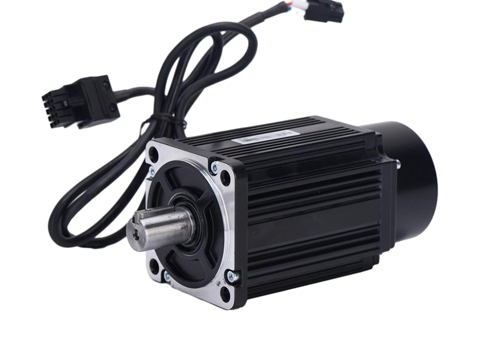
A Servo Motor utilizes a fundamentally different architecture. It relies on a low-pole-count design, often featuring just 4 to 12 poles. To achieve precision, it pairs this rotor with a high-resolution optical or magnetic encoder. The drive constantly reads this encoder. It creates a continuous, closed-loop feedback system. The controller knows the exact shaft position every microsecond and adjusts the current dynamically.
Consistent torque delivery: They maintain a flat torque curve. You get full rated power across the entire speed range.
High dynamic response: They handle rapid acceleration and sudden deceleration effortlessly.
Maximum efficiency: They only draw the exact electrical current required to move the current load. They run much cooler than open-loop alternatives.
Higher initial complexity: They require encoders, specialized feedback cables, and advanced drives.
Intensive commissioning: You must tune the Proportional-Integral-Derivative (PID) control loops precisely. Poor tuning causes erratic movement.
Standstill hunting: They constantly read the encoder and adjust position. This causes slight vibrations when holding a stationary load.
You should deploy these systems when unpredictability rules your environment. Robotic arms rely on them because payload weights change constantly. High-speed packaging machinery needs them to hit aggressive cycle times. CNC metal milling centers use them to power through varying material densities. Any system experiencing dynamic, fluctuating payloads requires closed-loop feedback to maintain absolute positional integrity.
To make the best engineering choice, you must compare these technologies directly against your application parameters. We evaluate them across torque delivery, fault tolerance, and system integration.
The torque-speed curve is the single most critical graph in motion control. If you operate between 0 and 1,000 RPM, an open-loop system usually wins. It generates massive torque relative to its frame size at these low speeds. However, physics changes as the shaft spins faster. Above 2,000 RPM, open-loop systems lose nearly all useful torque. A Servo Motor dominates this high-speed territory. It delivers a flat, continuous torque curve up to 3,000, 4,000, or even 5,000 RPM. You must map your application's top speed to these curves.
Certainty matters in automated manufacturing. Closed-loop systems provide absolute certainty. If a mechanical jam occurs, the drive detects the following error immediately. It triggers a fault, stops the machine, and alerts the operator. Open-loop systems assume the shaft reached the target. If it hits an obstruction, the controller blindly continues sending pulses.
We should also mention closed-loop steppers as a valuable bridge technology. They add an encoder to a traditional high-pole rotor. They correct minor positional errors on the fly. However, they do not solve the fundamental high-speed torque drop-off. They simply offer a safety net for edge cases where absolute position verification is necessary but speeds remain low.
Hardware footprint impacts your machine design heavily. When you scale up an open-loop system, you generally just run four wires to the motor. The drive enclosures remain compact. They generate less electrical noise.
Conversely, closed-loop systems require more complex cabling. You need separate power and feedback cables. The feedback cables require careful shielding to prevent EMI (Electromagnetic Interference). The drives often consume more panel space. If you build a multi-axis machine, this cabling overhead multiplies quickly. You must allocate sufficient space and routing channels in your mechanical design to accommodate this complexity.
Motion Control Architecture Comparison
Feature | Open-Loop System | Closed-Loop System |
|---|---|---|
Optimal Speed Range | 0 - 1,000 RPM | 0 - 5,000+ RPM |
Torque at Standstill | Maximum (Full Holding Torque) | Variable (Depends on load) |
Position Feedback | Assumed (No encoder) | Absolute (Continuous monitoring) |
Commissioning Complexity | Low (Plug and play) | High (PID tuning required) |
Energy Efficiency | Low (Draws constant current) | High (Draws only needed current) |
You can streamline your specification process by applying strict engineering rules. We developed a decision framework to eliminate guesswork. Follow these rules to align your mechanical needs with the correct hardware.
Rule 1: If the application requires speeds exceeding 2,000 RPM and involves dynamic load handling, default to a Servo Motor. Physics dictates this choice. Only low-pole architectures maintain torque at these velocities.
Rule 2: If the application requires high holding torque, low speeds, and simplified integration, default to a Stepper Motor. It delivers massive low-end power and locks into position flawlessly without tuning.
Rule 3: If you need low-speed performance but cannot risk a single missed step due to unpredictable friction, evaluate a Closed-Loop Stepper system. It serves as an excellent middle ground for specific edge cases.
You must understand what happens if you choose incorrectly. If you force an open-loop system into a high-speed, high-duty-cycle application, it will overheat. Thermal overload leads to premature insulation failure. You will also experience missed steps, destroying the manufactured parts.
If you force a closed-loop system into a simple, slow-moving application, you face different risks. You will waste days fighting PID tuning loops. The system might vibrate unacceptably at a standstill. You overcomplicate the machine architecture, leading to unnecessary commissioning delays.
Before you contact a vendor for procurement, you need hard data. Gather these three critical data points. First, calculate your inertia ratio. Keep it below 10:1 for standard dynamic systems. Second, define your continuous and peak torque requirements in Newton-meters (Nm). Finally, chart your maximum required RPM. Once you have these numbers, sizing software can pinpoint the exact frame size and winding configuration you need.
Neither motor is inherently superior. Their value is strictly tied to your application parameters. Open-loop high-pole motors master low-speed, high-torque precision. Closed-loop low-pole motors master high-speed, dynamic agility. You should always start your specification process with an accurate mechanical load profile rather than a predetermined technological preference.
Map your torque requirements across your entire speed range. Calculate your load inertia carefully. Evaluate your tolerance for control loop tuning. We highly recommend utilizing a motor sizing tool or downloading a technical spec sheet today. Contact an engineering sales team to validate your motion control architecture before finalizing your mechanical blueprints.
A: Yes, under specific conditions. Advanced microstepping drives divide a single mechanical step into thousands of increments. This provides excellent theoretical resolution. However, actual loaded accuracy depends on system friction and external forces. If external forces exceed the holding torque, the open-loop system will lose position. Closed-loop systems correct these deviations continuously.
A: A closed-loop stepper pairs a high-pole rotor with an encoder. It monitors shaft position to catch and correct missed steps dynamically. However, it does not replace low-pole technology for high-speed applications. It still suffers from steep torque drop-off at higher RPMs. It works best for low-speed tasks requiring absolute position verification.
A: No, but they frequently use them. A gearbox serves two purposes. It multiplies the continuous torque output, allowing a smaller motor to do heavy work. More importantly, it reduces the reflected load inertia back to the motor shaft. This inertia matching stabilizes the PID control loop, preventing erratic behavior.
A: This phenomenon is known as hunting. The system relies on a continuous feedback loop. At a standstill, the encoder detects microscopic positional shifts. The PID controller reacts instantly, injecting tiny amounts of current to hold the exact position. This constant micro-correction generates a high-frequency whine or slight vibration.


