
close
Choose Your Site
Global
Social Media


Views: 0 Author: Site Editor Publish Time: 2026-06-26 Origin: Site


Modern motion control systems demand absolute precision and reliable power. Standard microcontrollers and programmable logic controllers (PLCs) share a critical hardware limitation. They cannot supply the high current and massive voltage necessary to energize stepper motor coils directly. You need a dedicated intermediary component to bridge this extreme power gap.
Enter the motor driver. This vital device translates low-energy logic signals into precisely timed, high-power outputs. Without it, your motor simply will not turn or hold its position. Today, we are focusing entirely on understanding these internal electrical mechanics.
Knowing exactly how these components work is essential for specifying the right hardware. You will learn how to prevent unexpected torque loss at high speeds. We will also explore how to avoid catastrophic system failures caused by mid-band resonance or severe thermal overload. Let's dive into the core engineering principles driving these essential industrial components.
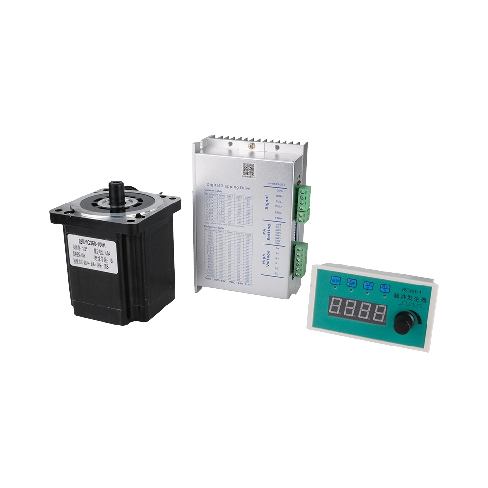
A stepper motor driver functions by sequencing high-current pulses to motor phases based on low-voltage step and direction logic signals.
Modern industrial applications primarily rely on constant current (chopper) drives rather than legacy constant voltage drives for superior high-speed torque.
Microstepping utilizes proportional phase currents to reduce resonance and improve motion smoothness, though it requires careful torque-loss calculations.
Proper evaluation requires matching the motor driver’s continuous current rating, thermal dissipation capabilities, and control interface to the exact application environment.
To understand motion control, you must map the signal flow. Systems rely on a strict hierarchy to move mechanical loads safely. The architecture separates decision-making logic from heavy power delivery.
Here is the standard signal chain flow:
The Controller (Brain): Generates low-voltage logic pulses based on programmed motion profiles.
The Driver (Muscle): Reads logic signals and switches high-voltage power accordingly.
The Motor (Actuator): Receives heavy current into its coils to generate electromagnetic force.
The controller talks to the motor driver using a standard interface. The most common protocol relies on Step and Direction (Step/Dir) signals. The "Step" pin acts as a clock. Every time this pin receives a rising edge pulse, the driver triggers a phase transition. One pulse equals one motor step.
The "Dir" pin dictates the sequencing order. A high signal might instruct clockwise (CW) rotation. A low signal reverses the sequence for counter-clockwise (CCW) rotation. The frequency of step pulses determines your motor speed.
Inside the driver, a circuit called an H-bridge performs the heavy lifting. Bipolar stepper motors have two distinct coil windings. Energizing these coils creates electromagnets. An H-bridge consists of four electronic switches, typically MOSFETs, arranged in an 'H' configuration around a single coil.
By opening and closing specific pairs of these transistors, the driver controls the exact direction of current flow. Reversing the current reverses the magnetic polarity of the stator tooth. Sequencing these polarity reversals across multiple coils forces the rotor to align and step forward. Precision switching defines the fundamental operation of every modern driver.
The method used to push current into motor coils drastically affects performance. Engineers categorize drives into two distinct architectures based on their power delivery methods.
Legacy systems often utilized constant voltage drives. These circuits apply a fixed power supply voltage directly across the motor winding. They rely entirely on the motor's internal resistance to limit the maximum continuous current.
While exceptionally simple, they suffer from a severe physical limitation. Motor coils act as inductors. Inductance resists rapid changes in electrical current. When the driver attempts to turn a coil on, the current rises slowly. At low speeds, this works fine.
At high rotational speeds, the driver switches phases rapidly. Because of inductance, the current never reaches its peak value before the next phase transition occurs. Consequently, high-speed torque plummets drastically. Engineers rarely recommend constant voltage drives for modern precision machinery.
Modern applications rely almost exclusively on constant current architecture. These are widely known as chopper drives. Instead of applying a fixed voltage, chopper drives utilize Pulse-Width Modulation (PWM) to actively monitor and regulate output.
Chopper drives run on a supply voltage much higher than the motor's nominal rating. This high voltage acts as a hammer. It forces current into the inductive coil extremely fast. The driver constantly monitors the rising current using an internal sense resistor.
Once the current hits a predefined limit, the driver "chops" or shuts off the power instantly. As the current decays naturally, the driver turns the power back on. This rapid switching cycle maintains a consistent average current. By overcoming inductance quickly, chopper drives maintain high torque levels even at extreme RPMs. They represent the definitive industry standard.
Feature | Constant Voltage (L/R) Drive | Constant Current (Chopper) Drive |
|---|---|---|
Current Control | Passive (relies on coil resistance) | Active (PWM sensing and chopping) |
Supply Voltage | Matches motor rated voltage exactly | Significantly higher than motor rating |
High-Speed Torque | Poor (current fails to build up) | Excellent (rapid current rise) |
Efficiency | Low (generates excess heat in resistors) | High (energy efficient switching) |
Early motion systems relied on full-step or half-step phase switching. The current was entirely on or entirely off. This digital approach creates harsh, jerky movements. Microstepping solves this by introducing analog finesse into a digital system.
Microstepping fundamentally changes how the H-bridge operates. Instead of binary switching, the driver outputs proportional phase currents. It modulates the current in the two coils using sine and cosine waveforms. By partially energizing both coils simultaneously at specific ratios, the magnetic forces balance out. This allows the rotor to hold positions between physical stator teeth.
A standard motor takes 200 physical steps per revolution. Using 1/16 microstepping, the driver commands 3,200 electronic positions per revolution.
Let us evaluate the specific features-to-outcomes of this technology:
The Benefit: Microstepping drastically reduces low-speed mechanical vibration. It mitigates destructive mid-band resonance commonly seen around 100 to 200 RPM. The acoustic profile becomes substantially smoother, eliminating the harsh grinding noises of full stepping.
The Risk: Many confuse electrical resolution with mechanical accuracy. Higher microstepping does not guarantee exact physical positioning. Furthermore, there is a severe holding torque loss. The incremental torque generated between a 1/32 microstep is only about 5% of a full step's torque. If dynamic friction or external loads exceed this tiny torque value, the motor will fail to move. It will skip microsteps until it snaps into the next full pole position.
Selecting the proper component requires careful mathematical evaluation. You cannot simply guess specifications. System reliability depends entirely on aligning the driver capabilities with the motor and the operating environment.
You must evaluate both continuous and peak current ratings. Motor datasheets specify phase current. Your driver's continuous RMS rating must comfortably align with or safely exceed this requirement. Selecting an underpowered unit leads to dangerous thermal throttling.
Supply voltage scaling is equally critical. To maximize high-speed performance, you calculate the optimal voltage based on motor inductance. A common engineering formula dictates maximum voltage as 32 multiplied by the square root of coil inductance in millihenries. Do not exceed the motor's insulation breakdown voltage, or you risk internal arcing and permanent failure.
High currents generate immense heat. When evaluating components, look at the internal resistance of the H-bridge MOSFETs, known as RDS(on). A lower RDS(on) value means less power dissipates as heat during switching.
Industrial reliability demands built-in safety features. Essential compliance mechanisms include thermal shutdown to prevent melting components. Over-current protection (OCP) saves the board if a short circuit occurs in the motor wiring. Under-voltage lockout (UVLO) prevents erratic behavior when the power supply struggles to keep up with sudden acceleration demands.
How the motor driver communicates dictates system complexity. Simple machines perform perfectly well with standalone Step/Dir interfaces. They are universally supported by almost all controllers.
Complex automated environments require intelligent drives. These utilize robust industrial communication protocols like SPI, EtherCAT, or CANopen. These networks allow the central PLC to adjust running currents on the fly. They also provide real-time diagnostics, reporting over-temperature warnings or stalled motor states back to the operator immediately.
Evaluation Metric | What It Means | Why It Matters |
|---|---|---|
Continuous RMS Current | Maximum current provided without overheating | Dictates continuous operating torque |
Maximum Voltage Rating | Highest safe DC input voltage | Determines high-speed RPM capabilities |
RDS(on) Value | MOSFET internal resistance state | Low values prevent excessive board heat |
Protocol Support | Step/Dir vs Industrial Networks | Defines integration and diagnostic capabilities |
Even perfectly specified hardware will fail if installed incorrectly. Several critical electrical phenomena routinely destroy poorly managed drives.
Inductive voltage spikes pose a massive threat. Also known as Back EMF (Electromotive Force), this occurs when external forces spin the motor manually. A spinning motor acts as a generator. It dumps massive unregulated voltage backward into the driver outputs. This instantly destroys the output MOSFETs. Disconnecting motor leads while the power supply is active causes similar destruction. Systems must include external flyback diodes or rely on heavy-duty built-in transient voltage suppression.
Managing mid-band resonance requires attention during setup. Stepper motors act like mass-spring systems. At certain specific frequencies, the stepping pulses excite the system's natural resonant frequency. The motor loses synchronization instantly and stalls violently. Poorly tuned drivers amplify this issue. You must select drivers equipped with active electronic damping or anti-resonance algorithms to push safely through these problematic speed zones.
Electromagnetic compatibility (EMC) and grounding issues plague many builds. High-frequency PWM chopping generates severe electrical noise. This noise easily couples into the low-voltage Step/Dir logic lines, causing the controller to read false steps. You mitigate this by employing strict wiring standards. Use twisted pair wiring for all motor connections. Ensure proper cable shielding tied to earth ground at one end only. Lastly, always specify drives featuring opto-isolated logic inputs to separate the noisy power ground from the delicate controller ground.
A stepper motor driver is never a simple commodity part. It acts as a foundational element dictating the ultimate accuracy, speed, and reliability of your entire motion control system. Understanding internal mechanics like H-bridge switching and PWM current chopping empowers you to make informed engineering decisions.
Follow a clear shortlisting logic. First, determine the exact continuous current required by your motor phase. Second, calculate the optimal supply voltage based on the coil inductance to guarantee high-speed torque. Third, evaluate the thermal dissipation environment and select the necessary control interface. Finally, ensure robust protection features exist to prevent electrical damage.
Your next step requires cross-referencing specific motor datasheets against verified driver specifications. Before committing to a final design, move directly into a prototyping phase using an evaluation board to test resonance profiles under real-world mechanical loads.
A: No. You must distinguish between absolute maximum peak ratings and safe continuous RMS operating current. Running at the absolute peak rating generates excessive heat. This triggers thermal shutdown or causes premature component failure. Always select a drive where your required continuous current falls well within its nominal safe operating range.
A: High-current chopping inherently produces heat due to MOSFET resistance. While warm operation is normal, extreme heat indicates issues. Common causes include inadequate heat sinking, poor cabinet ventilation, or setting the current limit higher than the motor actually requires for the load. Reduce the current setting if excess torque is unnecessary.
A: Yes, provided you wire it correctly. Unipolar motors usually have six or eight wires. To use a modern bipolar driver, you simply ignore the center tap wires on a 6-wire motor. You connect only the full coil ends. This converts the motor into a standard bipolar series configuration.
A: This is actually highly beneficial. Chopper drives actively regulate the current using PWM switching. The high voltage forces current into the inductive coils much faster, overcoming electrical resistance. This maintains high torque at high RPMs. As long as you stay within the driver's maximum voltage rating, it is completely safe.


