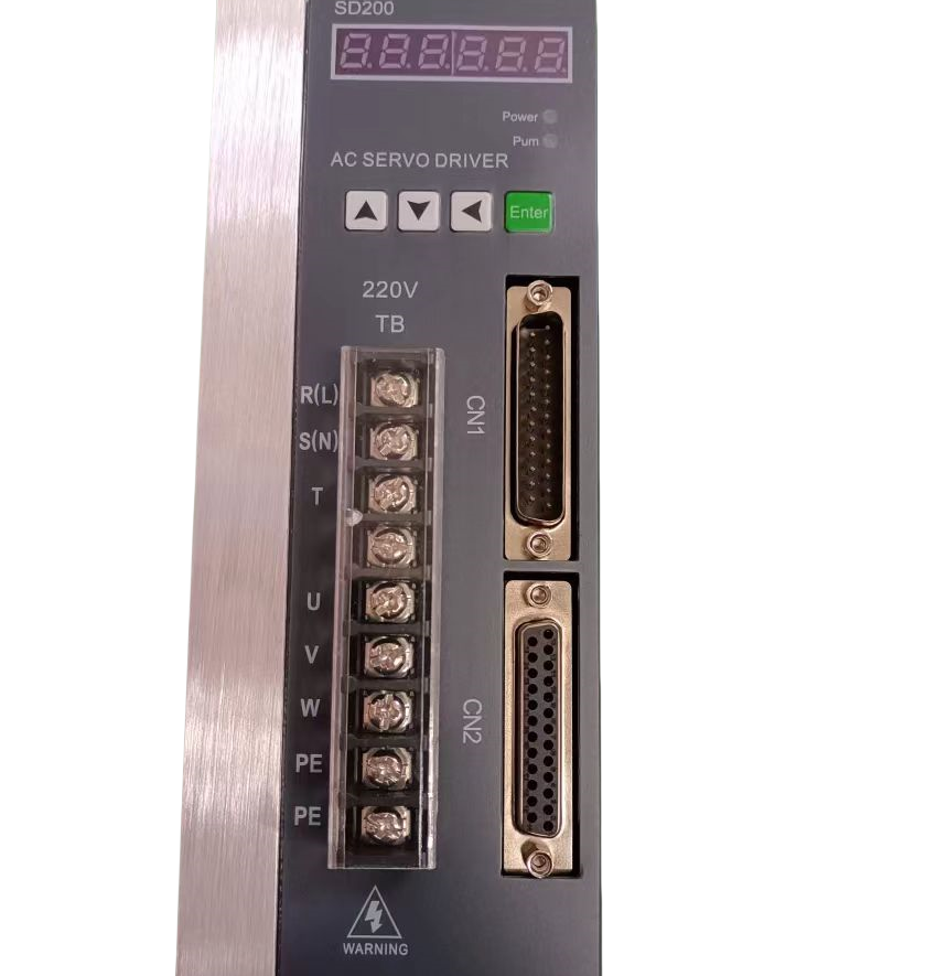
Microcontrollers and motors live in entirely different electrical environments. Logic circuits whisper in milliamperes and operate precisely at low voltages. They process information perfectly but lack physical strength. Motors operate differently. They roar for high voltages and massive currents to generate physical torque. You cannot connect a digital brain directly to a mechanical muscle. If you connect a standard microcontroller pin directly to a direct current (DC) motor, you will instantly fry the logic board.
A motor driver bridges this critical gap. It acts as the essential intermediary component in electro-mechanical design. The device translates low-power command signals from a controller into the high-power physical movement required by the load. Think of it as a current amplifier. It takes a delicate control signal and uses it to throttle a separate, much larger power supply.
This article decodes the internal mechanics of a motor driver. We will explore underlying architectures, discuss component limitations, and provide a practical framework. You will learn how to read datasheets like an engineer and select the exact hardware needed for your motion control system.
Key Takeaways
Core Function: Motor drivers act as current amplifiers, utilizing external power supplies to drive motors based on logic signals without frying the primary microcontroller.
The H-Bridge Mechanism: The foundational circuit for bi-directional control relies on strategically opening and closing solid-state switches (MOSFETs or BJTs).
Datasheet Reality Check: Continuous current ratings and internal resistance ($R_{DS(on)}$) are far more critical evaluation metrics than heavily marketed "peak current" capacities.
System Protection: Viable commercial motor drivers require integrated safeguards against inductive kickback (Back EMF), overcurrent, and thermal runaway.
The Engineering Problem: Why Direct Microcontroller Connections Fail
Engineers often face hardware failures when prototyping early motion systems. Direct connections between logic boards and mechanical loads inevitably end in catastrophic component failure. We must understand the underlying electrical conflicts to design robust systems.
The Power Deficit
Microcontrollers process data efficiently but output incredibly low power. A typical logic input/output (I/O) pin supplies roughly 20 to 40 milliamperes of current. Conversely, even miniature DC motors demand hundreds of milliamperes simply to overcome physical inertia. We call this the stall current. When a motor first begins to spin, or when it stalls under a heavy load, it acts almost like a short circuit. The power demand easily exceeds logic pin limits by a factor of ten or more. The logic pin simply melts under the load.
The Threat of Inductive Kickback (Back EMF)
Motors are essentially coils of wire spinning inside magnetic fields. This design creates a secondary problem. When you cut power to a spinning motor, mechanical inertia keeps the rotor turning. The motor instantly becomes a generator. It pushes energy backward into the circuit.
Voltage Spikes: This returning energy creates massive reverse voltage spikes.
Component Destruction: These spikes easily punch through the delicate silicon junctions of a microcontroller.
Flyback Necessity: We must channel this energy safely to ground before it reaches the logic stage.
The Two-Power-Supply Requirement
Robust designs always isolate the logic power supply from the motor power supply. When a motor draws its massive startup current, it pulls the system voltage down. If the logic board shares this power line, the sudden voltage drop triggers a brownout. The microcontroller resets repeatedly every time the motor attempts to start. A dedicated motor driver isolates these two domains. It uses the logic signal merely as a trigger while drawing heavy current from an independent battery or power unit.
How a Motor Driver Works: Core Mechanics and Signal Translation
Understanding internal mechanics helps you troubleshoot erratic system behavior. A motor driver fundamentally relies on solid-state switching to direct current flow.
The H-Bridge Architecture
The H-bridge serves as the foundation for modern bi-directional motion control. The circuit resembles the capital letter "H". The motor sits in the horizontal center line. Four electronic switches sit on the four vertical arms. By manipulating these four switches, we dictate exactly how current flows through the central motor.
Forward Motion: We close the top-left and bottom-right switches. Current flows through the motor from left to right.
Reverse Motion: We open the first pair and close the top-right and bottom-left switches. Current flows from right to left, reversing the rotation.
Braking: We close both bottom switches. This creates a short circuit across the motor terminals, stopping it abruptly.
Coasting: We open all switches. The motor spins freely until friction stops it.
Switching Technologies: MOSFETs vs. BJTs
Older designs relied on Bipolar Junction Transistors (BJTs). BJTs act like current-controlled valves. Unfortunately, they suffer from significant internal voltage drops, wasting energy as pure heat. Modern systems utilize Metal-Oxide-Semiconductor Field-Effect Transistors (MOSFETs). MOSFETs act like voltage-controlled resistors. They switch states incredibly fast and boast near-zero internal resistance. This efficiency allows modern integrated circuits to remain cool even under heavy mechanical loads.
Pulse Width Modulation (PWM) for Speed Control
Direction alone rarely satisfies engineering requirements. We also need precise speed control. We achieve this through Pulse Width Modulation (PWM). Instead of supplying a constant voltage, the logic board rapidly toggles the driver on and off thousands of times per second.
If we turn the switch on for 50% of the cycle and off for 50%, the motor behaves as if it receives exactly half the maximum voltage. You must ensure your hardware matches carefully here. The maximum switching frequency of your driver must accommodate the PWM output frequency of your logic controller. Mismatches cause erratic humming and severe thermal stress.
Solution Categories: Matching the Driver to the Motor Type
You cannot use a universal approach for motion control. Different mechanical architectures require distinct electronic control strategies. Selecting the wrong category leads to immediate incompatibility.
Driver Type
Hardware Complexity
Primary Use Case
Key Features
Brushed DC
Low
Continuous rotation, simple toys, basic pumps.
Basic H-bridge, bi-directional control, standard PWM regulation.
These represent the simplest and most common form of motion control. They utilize a standard H-bridge configuration. Their primary job involves simple forward and reverse switching combined with basic PWM speed regulation. They do not require complex timing algorithms from the microcontroller.
Stepper Motor Drivers
Stepper motors operate through discrete magnetic steps rather than continuous rotation. Their drivers require internal logic components called indexers. The logic board sends a simple "step" pulse and a "direction" signal. The driver then translates these basic signals into complex phase sequencing across multiple internal coils. Advanced stepper variants offer microstepping. This feature divides physical steps into hundreds of smaller electrical steps for extremely smooth positioning.
Brushless DC (BLDC) and Servo Drivers
Brushless systems eliminate physical brushes, significantly reducing mechanical wear. However, they demand highly complex electronic control. A BLDC driver coordinates three separate half-bridges. It must know the exact position of the rotor at all times to energize the correct coils. They achieve this using Hall-effect sensors or by measuring the back-EMF of unpowered coils. Servo drivers take this further by incorporating tight feedback loops to manage precise torque adjustments on the fly.
Evaluation Dimensions: Reading the Datasheet Like an Engineer
Marketing materials routinely exaggerate hardware capabilities. To design a reliable system, you must ignore the sales copy and evaluate the raw datasheet metrics directly.
Continuous Current vs. Peak Current
Never select your hardware based on peak current ratings. Manufacturers often highlight a massive "peak" number on the box. However, this rating represents the absolute maximum current the chip survives for just a few milliseconds. Continuous operating current serves as the true benchmark. This metric indicates what the chip handles safely all day long. Always evaluate continuous current alongside the system's ambient operating temperature.
Voltage Drop and $R_{DS(on)}$
Every switch creates some resistance. In MOSFET-based systems, we track this metric as $R_{DS(on)}$ (Resistance Drain-to-Source On). This number dictates how much power the chip wastes.
Power loss converts directly into heat. The calculation follows simple physics: Power Loss = Current Squared multiplied by Resistance. A lower $R_{DS(on)}$ means more electrical energy reaches the physical load and less energy turns into destructive waste heat. When comparing two similar chips, always choose the one offering lower internal resistance.
Thermal Dissipation Requirements
A continuous current rating remains conditional. It assumes you manage the heat properly. You must evaluate thermal dissipation strategies early in the design phase.
Passive Cooling: Suitable for low-power operations. It relies heavily on thick copper planes within the printed circuit board to pull heat away from the silicon.
Active Cooling: Mandatory for high-current industrial applications. It requires mounting physical aluminum heatsinks or integrating cooling fans over the chip casing.
Integrated Protection Circuitry
Modern commercial deployments fail without built-in safeguards. Bare-silicon H-bridges belong only in laboratory experiments. Production systems demand robust fault tolerance.
Protection Feature
Acronym
Operational Benefit
Under-Voltage Lockout
UVLO
Prevents erratic partial-switching states if the main power supply voltage drops dangerously low.
Over-Current Protection
OCP
Instantly severs power if a motor stalls or a physical wire short-circuits.
Thermal Shutdown
TSD
Shuts down the internal logic automatically before the silicon reaches its melting point.
Implementation Risks and Design Realities
Theoretical knowledge only takes you so far. Real-world implementation introduces unique parasitic challenges. We frequently see reliable ICs fail due to poor circuit integration.
Inadequate Decoupling and Bypass Capacitors
High-frequency switching generates massive electrical noise. When the driver toggles current rapidly, it creates heavy localized demand. If you omit bulk capacitance near the driver pins, the voltage sags momentarily. These high-frequency ripples travel back to the logic board. They cause erratic behavior, missed steps, and sudden microcontroller resets. Always place appropriately sized decoupling capacitors as physically close to the driver's power pins as possible.
Shoot-Through Currents
An H-bridge faces one fatal vulnerability. If the top and bottom switches on the exact same side close simultaneously, they create a direct path from power to ground. We call this a short circuit or "shoot-through". It destroys the hardware instantly in a puff of smoke.
This happens because transistors take a few nanoseconds to turn completely off. If the logic board commands an instant reversal, the newly activated switch turns on before the old switch fully turns off. Quality hardware integrates "dead time". This inserts a microsecond delay between state changes, guaranteeing one switch fully opens before the other closes.
Ground Loops and Isolation
Connecting massive mechanical loads and sensitive logic chips on the same board invites grounding issues. Heavy motor currents can lift the ground reference voltage. A logic chip expects ground to be zero volts. If heavy currents lift it to two volts, the logic board reads signals incorrectly.
Standard systems require careful "star ground" routing. High-voltage industrial applications require complete physical separation. Engineers use optoisolators. These devices transmit logic signals across a physical gap using light. They ensure high-voltage spikes cannot travel backward through ground paths into the sensitive logic domain.
Conclusion
A motor driver is never a one-size-fits-all component. You must evaluate the hardware through strict engineering dimensions. It requires precise matching to the mechanical stall current, the input logic frequency, and the ambient thermal constraints of your specific application.
Before purchasing hardware, take these concrete steps:
Calculate your system's maximum load current under worst-case mechanical stall conditions.
Add a strict 20-30% safety margin to this maximum calculation.
Compare continuous current limits across datasheets.
Evaluate the $R_{DS(on)}$ figures from reputable semiconductor manufacturers to ensure manageable heat generation.
By respecting these metrics, you build resilient systems capable of handling unexpected real-world mechanical stresses without electrical failure.
FAQ
Q: What is the difference between a motor driver and a motor controller?
A: A controller acts as the brain, generating the logic, timing, and decision-making signals. A driver acts as the muscle, receiving those weak signals and executing the high-power physical action by managing massive currents.
Q: Why do I need flyback diodes with a motor driver?
A: Flyback diodes safely route harmful high-voltage spikes away from sensitive components. These spikes occur when the collapsing magnetic field of a stopping motor acts as a generator. Many modern driver ICs now have these diodes built-in.
Q: How do I size a motor driver for my specific motor?
A: As a reliable rule of thumb, the driver's continuous current rating must comfortably exceed the motor's absolute stall current under the maximum expected physical load. Always include a safety margin.
Q: Can I drive multiple motors with a single driver?
A: Yes, if you wire the motors in parallel. However, the combined current draw must not exceed the driver's continuous limits. Furthermore, you will sacrifice independent control; they will spin exactly the same way simultaneously.