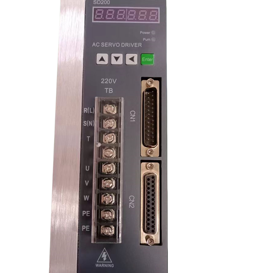
Stepper motors provide incredible precision for robotics and automation, but they cannot do it alone. They rely on a dedicated translator to convert low-voltage controller signals into high-power coil movements. This crucial middleman is the motor driver. Improper setup does not just leave you with a stubborn, non-functioning machine. It causes frustrating missed steps, harsh resonance issues, or catastrophic hardware failure. A single miswired phase can fry an expensive integrated circuit instantly. You need a rigorous approach to prevent these costly downtime scenarios. We will explore a step-by-step framework to securely wire, configure, and test your system based on established engineering practices. You will learn exactly how to validate hardware compatibility, master switch configurations, and confidently troubleshoot common setup errors.
Key Takeaways
Always verify motor phase pairs with a multimeter before wiring; never rely solely on manufacturer wire colors.
Match the motor driver RMS current setting to 80-90% of the motor’s rated current to balance torque output and thermal safety.
Isolate logic power from motor power to prevent electromagnetic interference (EMI) and signal noise.
**Never** disconnect or connect motor leads while the driver is powered, as the resulting voltage spike will destroy the driver.
Pre-Setup: Validating Motor Driver and Hardware Compatibility
Hardware mismatches guarantee project failure before you even strip the first wire. You must validate the electrical specifications between your power supply, the controller, and the coils. System integration requires precise calculations regarding current limits and voltage capacities.
Current Ratings: Peak vs. RMS
Stepper motors consume significant power. Manufacturers list current requirements differently. You will often see both Peak and Root Mean Square (RMS) values. RMS represents the continuous current a circuit can handle safely. Peak current denotes the absolute maximum short-term load.
Ensure the continuous RMS current of your chosen hardware can comfortably handle the phase current requirement of the motor. Running electronics at 100% capacity continuously generates excessive heat. Aim for a 20% headroom margin. If your stepper requires 3.0A per phase, select hardware rated for at least 3.6A RMS. This extends component lifespan and prevents sudden thermal shutdowns during intensive operations.
Voltage Overhead
Engineers often confuse a motor nominal voltage with the required power supply voltage. A stepper might list 3.3V on its datasheet. Supplying exactly 3.3V yields terrible performance. Inductance inside the motor coils resists rapid current changes. This resistance increases as the motor spins faster, creating back-electromotive force (back-EMF).
You need significant voltage overhead to overcome this back-EMF. Supplying 24V or 48V pushes the current into the coils much faster. This maintains high torque at high speeds. Check the maximum voltage limit of your hardware first. If it supports 48V, using a 48V power supply will drastically outperform a 12V supply. Always ensure your capacitors and integrated circuits are rated for the chosen input voltage.
Bipolar vs. Unipolar Configuration
Confirm the hardware type matches the motor type. Most modern industrial and hobbyist applications use 4-wire bipolar steppers. Bipolar motors utilize the entire coil winding for maximum torque. Unipolar motors feature 5 or 6 wires and utilize center taps, sacrificing torque for simpler control circuitry.
You must pair a bipolar motor with a bipolar drive circuit. Attempting to mix these topologies without specific wiring adaptations leads to erratic behavior. We will focus entirely on standard 4-wire bipolar setups, as they dominate current automation systems.
Essential Hardware Wiring Rules
Wiring mistakes destroy components instantly. A methodical approach prevents these unforced errors. You must verify every connection mechanically and electrically.
Identifying Phase Pairs
Generic wiring diagrams frequently mislead users. Cheap clone manufacturers often change wire colors between production batches. Never trust the datasheet colors implicitly. You must find the A+/A- and B+/B- pairs yourself.
Use the multimeter continuity method to identify phases safely:
Set your digital multimeter to the continuity or resistance (Ohms) setting.
Pick any random wire from the motor. Connect one multimeter probe to it.
Touch the second probe to the remaining wires one by one.
When the multimeter beeps or shows low resistance (usually 1-5 Ohms), you have found a phase pair (e.g., A+ and A-).
The remaining two wires form the second phase pair (B+ and B-).
Common Mistake: Wiring A+ to B- crosses the phases. The motor will merely vibrate violently without rotating. Always label your identified pairs before making permanent connections.
Power Supply Connection
DC input requires careful planning. Proper grounding dictates system stability. Connect the DC negative terminal directly to the central grounding point. Avoid daisy-chaining ground wires across multiple devices. Daisy-chaining creates ground loops, introducing severe noise into your control signals.
Select appropriate wire gauges for the main power input. Under heavy loads, thin wires act like resistors. This causes severe voltage drops. A 24V supply might drop to 18V at the terminal block if the wires are too thin. Use 18 AWG or thicker wire for any run exceeding 3 amps. Keep these DC power lines physically separated from your low-voltage logic wires to prevent inductive noise coupling.
Control Signal Wiring (PUL, DIR, ENA)
The controller sends Pulse (PUL), Direction (DIR), and Enable (ENA) signals. You can wire these in two primary ways: Common Anode or Common Cathode. Your choice depends entirely on your microcontroller or PLC output type.
Common Anode: Tie all positive input terminals (PUL+, DIR+, ENA+) to a shared +5V source on the controller. The controller then sinks current by pulling the negative terminals (PUL-, DIR-, ENA-) to Ground to trigger a signal.
Common Cathode: Tie all negative input terminals (PUL-, DIR-, ENA-) to a shared Ground. The controller sources current by sending +5V to the positive terminals to trigger a signal.
Best Practice: Watch your logic voltage levels carefully. Many industrial PLCs output 24V logic signals. Most standard inputs expect 5V logic. Connecting 24V directly to a 5V optocoupler will incinerate the LED inside. You must install inline resistors (typically 2kΩ) to drop the 24V signal down to a safe 5V level.
Configuring DIP Switches: Current and Microstepping
Mechanical DIP switches dictate how the system behaves. Incorrect switch placement leads to overheating or jerky movements. You must translate your motor specifications into the correct switch array.
Setting the Output Current
Start with a conservative baseline. Set the peak output slightly below the motor maximum rated current. If your motor handles 3.0A, configuring the switches for 2.8A extends hardware lifespan significantly. The tiny sacrifice in holding torque usually goes unnoticed, but the thermal benefits are massive.
Look for the "Standby Current" feature. This is frequently assigned to Switch 4 (SW4). When enabled, the circuit automatically halves the holding current when it detects no step pulses for a fraction of a second. Halving the current reduces I⊃2;R power dissipation by 75%. This prevents the motor from becoming dangerously hot while idling. Always enable half-current standby unless your application requires absolute maximum holding torque during stationary periods.
Selecting Microstepping Resolution
Microstepping divides a standard 1.8-degree physical step into smaller increments. A standard motor requires 200 pulses for one full revolution. Setting the microstepping to 1/8 means the motor now requires 1,600 pulses per revolution. Setting it to 1/32 requires 6,400 pulses.
Higher microstepping yields incredibly smooth motion. It eliminates low-speed resonance and reduces acoustic noise. However, this introduces a severe trade-off. It requires a massively higher pulse frequency from the controller. A basic Arduino tops out around 4,000 pulses per second. If you set the microstepping too high, the microcontroller simply cannot generate signals fast enough. Your maximum speed will plummet.
Recommend starting point: Use 1/8 or 1/16 step resolution. This provides an excellent balance for most CNC and robotics applications. It smooths out vibrations while keeping the processing load manageable for standard controllers.
Microstep Setting
Pulses Per Revolution
Smoothness
Controller Processing Load
Full Step (1/1)
200
Very Low (High Vibration)
Very Low
1/8 Step
1600
Good
Moderate
1/16 Step
3200
Excellent
High
1/32 Step
6400
Maximum
Very High (May bottleneck MCU)
Power-On Sequence and Thermal Management
You have wired the phases. You have flipped the DIP switches. Do not simply plug the system into the wall. The initial power-on phase requires a strict sequence to avoid unexpected mechanical crashes.
The "First Boot" Checklist
Perform a final audit before flipping the switch. Verify the power supply voltage with a multimeter before attaching it. A 48V supply accidentally cranked to 55V will trigger over-voltage protection or destroy components.
Check polarity: Ensure V+ and GND are not reversed. Reverse polarity destroys integrated circuits immediately.
Verify Enable (ENA) state: Ensure the ENA pin is correctly configured. In most systems, leaving ENA disconnected defaults to "Enabled." The motor should lock rigidly upon power-up. If it spins freely, check your ENA logic.
Clear the travel path: Disconnect the motor shaft from belts or lead screws. This prevents machine damage if the motor spins out of control due to a wiring fault.
Cooling Requirements
Stepper systems run notoriously hot. A motor operating at 80°C (176°F) is completely normal. However, the electronics cannot survive those temperatures. You must manage heat effectively.
Passive cooling works well for setups drawing under 3 amps. Ensure the aluminum heatsink fins orient vertically. This allows natural convection to carry hot air upward. Never mount a heatsink upside down or horizontally if you rely on passive airflow.
Active cooling becomes mandatory for continuous operation above 3 amps. Enclosing a high-amperage motor driver inside a sealed, unventilated control box guarantees failure. The ambient temperature inside the box will skyrocket. Thermal shutdown circuits will trip randomly, ruining your workpiece. Install intake and exhaust fans in your enclosure to guarantee continuous air turnover.
Troubleshooting Common Setup Failures
Even meticulous engineers face unexpected behavior during commissioning. Troubleshooting requires isolating variables systematically. Below is a diagnostic framework for resolving the most frequent setup failures.
Symptom: The motor vibrates loudly but does not rotate.
Diagnosis: You have incorrect phase wiring. The controller is pulsing, but the magnetic fields are fighting each other. You likely swapped a wire from Phase A into the Phase B terminal. Power down immediately. Re-test your wire pairs using the multimeter continuity method and re-seat the connections.
Symptom: The system overheats and shuts down randomly.
Diagnosis: The hardware is entering thermal protection mode. Your current DIP switches are set too high for the motor requirements. Alternatively, you lack adequate airflow. Reduce the peak current setting by one tier. Ensure the standby current (SW4) is active. Verify cooling fans operate correctly.
Symptom: The system loses steps during rapid movements.
Diagnosis: The motor lacks the torque needed at high speeds. Your power supply voltage is too low to overcome the back-EMF generated by rapid rotation. If the voltage is adequate, your software acceleration settings are too aggressive. The motor physically cannot accelerate the attached mass fast enough. Lower the acceleration curve in your controller software.
Symptom: Erratic movement or random direction changes.
Diagnosis: You have electromagnetic interference (EMI) corrupting the low-voltage logic lines. High-power phase wires are inducing noise onto the sensitive DIR signal line. The controller sees a false "change direction" command. You must physically separate power cables from logic cables. Always use shielded, twisted-pair cables for your controller logic connections. Ground the shield at one end only to prevent ground loops.
Conclusion
Setting up automation hardware demands methodical validation. You cannot cut corners. Verify your phase pairs manually. Calculate your RMS current limits conservatively. Configure your microstepping switches to balance motion smoothness and processing power. Test everything under safe conditions before linking the mechanics.
Your immediate next step is running a slow, no-load test program. Send a basic G-code or pulse sequence to rotate the shaft precisely one revolution. Measure the outcome. Once you confirm the shaft behaves predictably without a load, you can attach your belts or lead screws.
Finally, document your final DIP switch configurations and wiring schematics. Stick a printed label inside your control box. Months or years from now, when you need to replace a worn component, this documentation will save you hours of reverse engineering. Treat the setup phase as the foundation of your entire machine reliability.
FAQ
Q: What happens if I wire the stepper motor phases backward?
A: Reversing a single phase simply reverses the motor default direction of rotation. For example, swapping the A+ and A- wires will make a clockwise command turn counter-clockwise. It will not cause hardware damage or electrical shorts.
Q: Can I run a 3A stepper motor on a 2A motor driver?
A: Yes, but the motor will only produce a fraction of its rated torque. It is completely safe for the motor coils. It remains safe for the electronics provided you do not push the circuitry beyond its thermal limits. You will experience stalling under load.
Q: Why does my setup have a high-pitched whine?
A: This high-pitched whine is a common symptom of chopper drive frequencies interacting with the motor coils. The PWM frequency essentially turns the motor into a crude speaker. You can often resolve this by adjusting your microstepping resolution or enabling advanced features like stealthChop on modern integrated circuits.